Synchronization
Synchronization allows you to couple other audio programs or studio hardware such as tape machines, drum machines, video recorders, or sequencers to Samplitude so that all devices and programs run in time or clock synchronization, i.e. musical tempo, playback or recording speed, and position at the devices involved match.
Samplitude can be configured for synchronization as a master (leader) or as a slave (follower). As a master, it generates the synchronization data for other components in the system. As a slave, Samplitude receives the synchronization data and follows it during playback and recording.
To switch synchronization on and off, use this button on the transport console or menu File > Project properties > Synchronization active (keyboard shortcut: G).
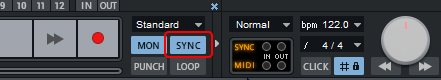
All settings for the different synchronization options are located in the dialog Synchronization, which you open with a right click on this button or via menu File > Properties of the project > Synchronization settings… (keyboard shortcut: Shift + G).
Synchronisation Protocols
The protocols (data formats) used for synchronization contain information about the start position, start and stop commands and, in some formats, position information that is constantly transmitted.
Samplitude receives and transmits the synchronization protocols MIDI Clock (MC), MIDI Time Code (MTC) and the ASIO Positioning Protocol (APP).
MIDI Clock
The MIDI Clock is pure tempo information, the time reference is the musical tempo. For this purpose 24 Timing Clocks (MIDI System Realtime Message 0xF8) are transmitted per quarter note (24 ppqn - pulses per quarter note). Since the MIDI clock is based on the tempo as a reference, the number of ticks output depends on the tempo of the generating device. The receiving device determines the current tempo from the number of clocks received per elapsed time. But beyond that MIDI Clock does not transport any current information about the time position in the project.
With the messages Start 0xFA (start at project start), Stop 0xFC and Continue 0xFB (start at position) the playback of the receiving device can be started and stopped synchronously. Before each Start or Continue message, the Song Position Pointer (SPP) 0xF2 is also sent. It indicates the current bar position in 1/16 notes and thus allows synchronization of the project positions at least at playback start.
MIDI clock synchronization is suitable for synchronizing devices with tempo and clocks as time reference like hardware sequencers or the LFOs or arpeggiators of external synthesizers.
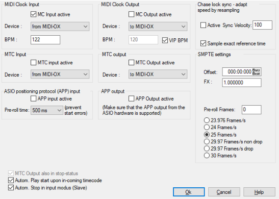
At MIDI Clock Input/MIDI Clock Output in the dialog Synchronization you activate the synchronization via MIDI Clock:
-
With MC Input active you activate the MIDI clock synchronization of Samplitude as slave (follower). At Device, select the MIDI device from which the MIDI Clock signal is to be received for synchronization.
Samplitude is not able to adjust its project tempo to an incoming MIDI clock. Instead you have to set the tempo of the received MIDI clock at BPM. The project tempo should also correspond to this value, so that in the project the time display in bars matches the MIDI clock. For synchronization with MIDI Clock we recommend to use Samplitude as master or, if possible, to use MTC (see below).
-
With MC Output active you activate the MIDI clock synchronization of Samplitude as master (leader). At Device, select the MIDI device through which the MIDI Clock signal is to be sent.
The option VIP BPM ensures that the current project tempo is used for the MIDI clock. If you disable it, you can also send the tempo set at BPM.
MIDI Time Code (MTC)
With the MIDI Time Code (MTC) the current time position is transmitted continuously, via a MIDI port in the form of a SMPTE time code, which is transmitted as MTC Quarter Frame (MIDI System Realtime Message 0xF1) four times per frame. Each message contains a part of the absolute time position as data byte. Eight such MTC Quarter Frames result in the transmitted time code as an absolute time position in the project in hours:minutes:seconds:frames. This means that the frame rate in the components involved must be the same for MTC synchronization to work. Therefore, select the same frame rate in the SMPTE settings (see below) and on the device involved.
At MTC Input/MTC Output in the dialog Synchronization you activate the synchronization via MTC:
-
With MTC Input active you activate the MTC synchronization of Samplitude as slave (follower). At Device select the MIDI device from which the MTC signal is to be received for synchronization.
-
With MTC Output active you activate the MTC synchronization of Samplitude as master (leader). At Device, select the MIDI device through which the MTC is to be sent.
There is no transmission of the playback state as with MIDI Clock, since it is clear from the change (or non-change) of the time code whether playback is running or not. For this, there are some MTC specific options that affect the playback and recording behavior:
-
MTC output also in stop state: Eight MTC messages must be transmitted within two frames to transmit a complete timecode. If with Samplitude as master (leader) the time code is transmitted just with the start of the playback, the slave (follower) component synchronizes to the current position only after a delay of one frame, so it is in a wrong position for a short time after a manual position change while in stopped state (moving the play cursor).
If the option is active, the current time position is sent continuously even when playback is stopped to avoid this. The option is also important for devices such as tape recorders or video recorders, so that they can detect these position changes in the stop state and transport the tape to this time position.
-
Automatic play start on incoming timecode: If Samplitude receives timecode as a slave (follower), Samplitude starts playback as soon as a timecode is received.
-
Automatic stop in input mode (slave): If Samplitude receives MTC as slave (follower) and the corresponding track is ready for recording, Samplitude starts recording as soon as MTC is received. If there is no more MTC, Samplitude stops recording and automatically goes into playback mode. When timecode is received again, Samplitude starts playback. If you want Samplitude to continue recording when you receive MTC again, uncheck this option.
APP (ASIO Positioning Protocol)
The ASIO Positioning Protocol allows the transmission of synchronization information via the digital inputs or outputs of the sound card (SPDIF, ADAT) or special interfaces (LTC, Video Burst In). This allows you to synchronize with timecode as withMTC without the need for an additional MIDI connection. This protocol is only supported by very few, special audio cards.
Activate the operation as slave (follower) or master (leader) with the corresponding options APP Input active or APP Output active. With active input, you can set a Pre-roll time to ensure stable synchronization.
SMPTE settings
SMPTE Timecode is a conventional synchronization standard for linking different audio and imaging devices via absolute time reference. With each SMPTE message, the exact amount of time that has elapsed since the start of the project is sent.
The SMPTE timecode uses the units hours:minutes:seconds:frames. The concept of "frames" originates from the film and video industry, which the SMPTE code was originally developed for. The frame rate corresponds to the number of frames per second common in film and video.
Go to SMPTE Settings and select the appropriate project frame rate here. This frame rate is used for synchronization with MTC. If you use video files in the project, you should also match their frame rate.
-
SMPTE offset: Here you can specify an offset that is subtracted from the received SMPTE time before the time is used for synchronization. An offset of 01:00:00:00 (1 hour) therefore allows you to synchronize a tape with an SMPTE code that starts at 1 hour. The SMPTE offset behaves relative to the project start time.
-
FX: This legacy option can be used to compensate for synchronization inaccuracies in old projects. It should not be changed for working with current projects.
Pre-roll Frames: Here you can enter a number of frames that Samplitude should ignore before synchronization starts. This can be used to respond to the fact that analog devices first need a certain amount of time to reach the correct speed. To prevent Samplitude from synchronizing to an invalid time, the preroll frames are skipped before the synchronization takes effect.
Chase Lock Sync
With chase lock synchronization, audio playback from Samplitude in slave mode exactly follows a received timecode signal by changing the playback speed through real-time resampling. Thus, Samplitude is able to synchronously follow a timecode source with variations such as analog tape machines or VCRs over a longer period of time if the timecode is located on a track of a multitrack tape machine, for example.
-
Active: Here you activate Chase Lock synchronization.
Note: Note that if Chase Lock is enabled, real-time resampling will also occur during recording according to a received timecode with all possible fluctuations. This causes increased CPU load and may result in unwanted changes to the audio material if this is played later with other timecode references.
-
Sync Velocity: The sync velocity influences the speed of the tempo adjustment. The larger the value, the faster Samplitude follows a tempo change of the master device, but the greater the pitch fluctuations in the audio material. The default value for the sync velocity is 100. Increase it if the synchronization is not exact.
-
Sample exact reference time: If you select this option, Samplitude takes the time position of the sound card as clock reference (timer) and not its own internal timer. This ensures sample-exact synchronization between the recorded audio material and the sync signal.
If you use Wordclock for digital sample rate synchronization of your devices with Samplitude, you should not use Chase Lock.
Wordclock Sync
When digital data streams are exchanged between multiple devices using protocols such as ADAT, SPDIF or MADI, a clock reference must be established throughout the interconnected system. The clock signal is transmitted via the digital input and can come from involved computers, but also external devices like converters or mixers can serve as clock reference. For these systems, there can be only one master but several slaves. This digital word clock is not a time code, no position information is transmitted. The clock signal is just a digital pulse and is used to synchronize the timing between the connected devices and to keep the sample rate constant everywhere to prevent transmission errors. Professional digital audio devices normally feature a word clock input and are able to generate and receive a clock signal.
To set the clock source, use the Clock Source menu in the Audio Settings. There the ASIO driver of the sound card may provide options to synchronize the sound card to an external clock source.