Advanced Dynamics
All dynamic effects have a common working principle: the level of an audio signal is amplified, and the degree of amplification is simultaneously controlled by the level of this signal. When the level goes above or below a certain point (Threshold), the amplification changes to achieve a certain effect: For example, you get a compressor when the amplification is reduced above the threshold, or a noise gate when the amplification is reduced to 0 below the threshold, suppressing the signal.
The Advanced Dynamics effect processes the dynamics of a signal through a combination of several dynamics stages: a noise gate, two compressor/expander stages, and a limiter. The resulting characteristic curve of this dynamic effect can be edited graphically and parametrically.
|
|
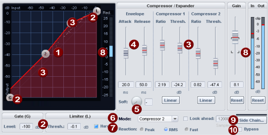
Characteristic curve: The characteristic curve represents the transfer function from the input level to the output level. When you play back audio, you will see the current input and output levels of the signal as a white cloud of dots over the characteristic curve. With this Dynamic Scope the change of levels is constantly visualized by Advanced Dynamics. You can edit the transfer characteristic graphically by moving the points on the curve or parametrically by changing the parameters of the characteristic sections with the sliders. If you right-click on a point, you will get an input field in which you can directly enter the position of a point in the characteristic curve. |
|
|
The control points G and L of the characteristic curve control the upper and lower limit of the characteristic curve , the Gate and the Limiter. Below the characteristic curve are the associated parameters.
Limiter (L):
|
|
|
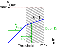
The points 1 and 2 control the two characteristic curve sections for the compressor/expander stages. The horizontal position determines the thresholds of the stages (Thresholds), the vertical positions result in different rises for the curve sections, which can also be expressed as Ratio: With a ratio < 1 the stage works as an expander, with settings > 1 as a compressor. If a stage works as a compressor, it means that the gain above the threshold is reduced: For example, with a set ratio of 2, this means that if the input level is increased by 3 dB, the output level will only be increased by 1.5 dB. High levels (above the threshold) are therefore amplified less than low levels, reducing the dynamic range and compressing the signal. The larger the ratio value, the stronger the compression.
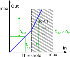
The dynamic range of an input signal (exemplarily marked by the green lines) is reduced by the compressor. If a stage works as an expander, it means that the gain above the threshold is increased: For example, with a set ratio of 0.5, this means that increasing the input level by 3 dB will increase the output level by 6 dB. High levels (above the threshold) are thus amplified more than low levels, increasing the dynamic range and expanding the signal. The smaller the ratio value, the stronger the expansion.
The dynamic range of an input signal (exemplarily marked by the green lines) is increased by the expander. |
|
|
Envelope: The time constants regulate the sound characteristics significantly, so certain time constants can lead to distortion effects or to "pumping".
|
|
|
Soft: With this parameter you specify a rounding of the characteristic curve at the folding points. If the change between uncompressed and compressed signal is clearly apparent, i.e. the signal level fluctuates around the folding point, "Soft" achieves a smoother transition. |
|
|
Mode: These are typical use cases for the Advanced Dynamics. They specify settings that make the graphical editing of the characteristic curve easier. The mode selection limits the number of applicable parameters, e.g. when used as a pure limiter. |
|
|
Reaction:
|
|
|
Level:
|
|
|
Sidechain: If this option is activated, another signal from one or more other tracks is used for level control instead of the processed signal itself. In The Sidechain... button opens the Sidechain menu:
The lower part of the menu lists all the tracks from which you can select one or more as sidechain sources. In the mixer channels used as sidechain signal, a separate sidechain bus is created that sends directly to the sidechain input. The signal tap of the sidechain send is preset to Pre-Fader. This causes the sidechain signal to remain independent of the volume setting of the sending channel. |
|
|
Bypass: This allows you to temporarily disable the effect in order to compare the unprocessed signal with the processed signal. |